How to Design Parts for CNC Machining: A Beginner’s Guide
Designing parts for CNC machining isn’t just about creating a good-looking 3D model; it’s about engineering functionality, precision, and manufacturability into every curve and corner. Whether you’re working on your first prototype or aiming to mass-produce components, understanding how to design effectively for CNC machining will help you avoid costly mistakes, reduce lead times, and achieve high-quality results.
This guide walks you through all the essential elements of CNC part design, starting from the machining process itself to detailed design guidelines, best practices, and technical drawing essentials.
What is the CNC Machining Process?
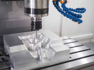
CNC machining is a subtractive manufacturing technique where raw material is removed using various cutting tools controlled by computer instructions. CNC stands for Computer Numerical Control, which refers to the automation of machine tools via pre-programmed software.
Here’s how the process works:
- Design Phase (CAD): The part is first created using CAD software such as SolidWorks, Fusion 360, or AutoCAD. This design includes every dimension, feature, and surface requirement.
- Programming Phase (CAM): The CAD file is then imported into CAM software, where tool paths are created, and parameters like cutting speed, tool selection, and passes are defined. The software generates G-code, which the CNC machine reads.
- Setup Phase: The machinist sets up the workpiece, installs the tools, and aligns the machine based on the origin defined in the CAD file.
- Machining Phase: The machine begins the cutting process, following the code precisely. Tools cut, drill, or mill the part into shape.
- Post-Processing: Once machining is done, the part may require additional steps like deburring, sanding, coating, or quality inspection.
This process is widely used in industries like medical, automotive, and consumer electronics, due to its high precision and repeatability. For a more comprehensive understanding of how CNC machines work, check out our detailed guide about CNC machines.
What Are the Main Restrictions of CNC Design?
Despite its power, CNC machining does have its limitations, mostly dictated by the physics of cutting tools and machine motion. Designing with these restrictions in mind is vital to ensure that your part is actually machinable without excessive time or cost.
Tool Accessibility
Every surface and internal feature must be reachable by the cutting tool. If a surface is blocked by another feature or lies behind an internal wall, the machine simply can’t reach it unless you use more complex 5-axis machines or special tooling, which increases cost.
Tip: Avoid designing hidden internal cavities or narrow channels that can’t be accessed directly.
Tool Geometry
Most CNC tools are cylindrical, which means they leave behind curved internal corners. Sharp internal 90° angles are not possible with a standard end mill. You must add fillets or internal radii to accommodate tool geometry.
Example: For a 10 mm diameter tool, use an internal corner radius of at least 6 mm.
Minimum Feature Size
Cutting tools have a physical diameter and length, limiting the minimum detail they can achieve. Smaller tools can create finer features but are also weaker and more prone to breakage.
Rule of Thumb: Avoid features smaller than twice the tool diameter to reduce risk. Kirmell’s CNC machining services are equipped to handle such precision requirements, ensuring that your undercut features are produced accurately without unnecessary delays. Contact us today about your project and get a quote.
Material Limits
Some materials are harder to machine than others. For example, stainless steel takes longer and wears tools faster compared to aluminium. Extremely hard or brittle materials may require slower cutting speeds or specialised tools.
What Are CNC Design Guidelines
Designing with CNC capabilities in mind helps ensure parts are cost-effective, quick to produce, and easy to machine without requiring multiple setups or custom tooling.
Internal Radii
- Always apply radii to internal corners.
- A minimum radius of 1.5x the cutter radius prevents excess tool wear and stress.
- Larger radii enable faster machining and better chip removal.
Hole Sizes and Depths
- Stick to standard drill sizes (e.g., 6 mm, 10 mm, etc.).
- Avoid hole depths greater than 4x the diameter.
- Deep holes may require peck drilling or specialised tools, adding time and cost.
Wall Thickness
- Thin walls can vibrate or deform during machining.
- Maintain a minimum of 1.5 mm for metal parts and 2 mm for plastics.
- For taller walls, increase the thickness proportionally to height.
Cavity Depth
- Avoid overly deep pockets.
- Keep cavity depth less than 4x cavity width.
- If needed, break the cavity into multiple shallower regions.
Text and Logos
- Engraved features should be at least 0.5 mm wide and 0.3 mm deep.
- Use simple fonts and avoid very small text sizes that require fine tooling.
How to Set Up a CNC Machine and Part Orientation
Each CNC setup (or reorientation) increases cost and risk of error. A well-designed part requires the fewest possible setups, ideally just one or two.
Part Orientation Tips:
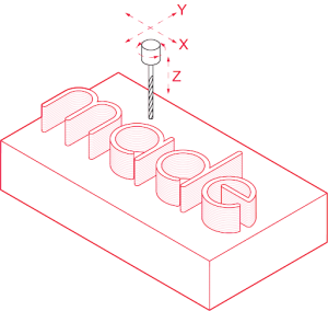
- Align features along the X, Y, and Z axes for easier access.
- Avoid designing features on surfaces that require flipping or complex fixturing.
- Plan features so that multiple surfaces can be machined in the same setup.
Pro Tip: Use symmetrical designs where possible to simplify fixturing.
Fewer setups lead to faster turnaround and more consistent results.
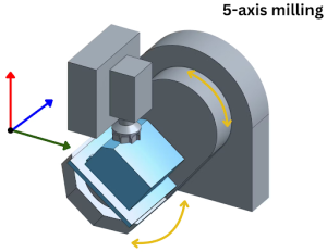
What is 5-Axis CNC Machining?
5-axis CNC machining is an advanced manufacturing process that goes beyond the capabilities of traditional 3-axis CNC machines. While 3-axis machines operate along the X, Y, and Z linear axes, 5-axis machines add two additional rotational axes, allowing for far greater flexibility and precision in machining complex parts. This added movement enables the machine to approach the workpiece from virtually any angle, making it ideal for parts with intricate geometries or features on multiple surfaces.
Benefits of 5-Axis CNC Machining
One of the primary advantages of 5-axis machining is the ability to machine all sides of a part in a single setup. This reduces the need for repositioning or multiple fixtures, which saves time and minimises the chance of human error.
The process is especially useful for creating highly complex components such as turbine blades, medical implants, or aerospace parts with compound curves and deep cavities. Fewer tool changes and reduced manual intervention also contribute to faster production cycles and improved overall accuracy.
When to Choose 5-Axis Machining
5-axis CNC machining is the preferred choice when your part design includes features on multiple angled planes, or when tight tolerances and a superior surface finish are critical. It is also ideal for parts with undercuts, deep pockets, or compound curves that are difficult or even impossible to machine using a 3-axis setup.
Although the hourly cost of 5-axis machining is typically higher, the increased precision, reduced handling, and faster turnaround times often lead to better value and superior final results.
Undercut Design for CNC machining
An undercut in CNC machining refers to a recessed feature, like a groove or notch, that cannot be accessed directly from the top or side of the part using standard tools. These features often occur on the inside walls of pockets or cavities and can present significant challenges in both programming and tooling.
When incorporating undercuts into your part design, it’s important to ensure adequate tool clearance. A practical guideline is to maintain at least four times the undercut depth as clearance between the undercut wall and any adjacent internal walls. This extra space allows the tool to reach the feature without interference.
Options for Machining Undercuts:
- Use specialised tools like lollipop or T-slot cutters.
- Modify the design to avoid the undercut if it’s not essential.
- Consider breaking the part into multiple assembled components to eliminate the need for undercutting.
Undercuts often require custom CAM programming, longer machining time, and increased setup complexity.
Drafting a Technical Drawing
Although modern CNC machining heavily relies on 3D CAD models, 2D technical drawings are still an essential part of the manufacturing workflow. These drawings serve as a universal language between engineers, machinists, and quality inspectors, ensuring that nothing is left to interpretation.
A well-structured technical drawing not only provides clarity but also prevents production errors, especially when you’re outsourcing your machining work to an external machine shop. In many cases, machine shops will not begin fabrication without an approved technical drawing, even if a 3D file is provided.
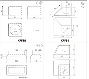
Key Elements to Include in Technical Drawing of CNC Machining:
- Orthographic views (top, front, side).
- Critical dimensions and tolerances (e.g., ±0.1 mm).
- Notes on materials, surface finish, threads, heat treatment, or coatings.
- Section views for complex internal features.
- Part title, units, scale, revision number, and designer’s name.
What Are the Best Practices for CNC Machining?
Here’s a round-up of professional practices that every beginner designer should follow:
Design for Manufacturability (DFM)
Design with CNC limitations in mind. Don’t create features that are theoretically possible but practically unachievable.
Use Standard Tooling Sizes
Stick to common tool diameters and drill sizes to avoid extra costs and lead times for custom tooling.
Avoid Over-Tolerancing
Only apply tight tolerances (like ±0.01 mm) to functional or mating features. Tight tolerances slow down production and increase inspection requirements.
Choose the Right Material
Aluminium, brass, and plastics like Delrin are ideal for beginners. Titanium and stainless steel are harder to machine and more expensive.
Minimise Setup Changes
Design parts that can be machined in a single orientation. Fewer reorientations = fewer errors and lower costs.
Test with Prototypes
If you’re unsure how a design will machine, start with a prototype using a softer material like aluminium or plastic before moving to final production.
Consult Your Machinist
If working with a machine shop, share your early designs and get feedback. Most shops are happy to suggest improvements to make your part easier to produce.
Conclusion
CNC machining is a powerful and flexible manufacturing method but to get the most out of it, your part must be designed with precision, practicality, and process knowledge in mind. By following the guidelines in this beginner’s guide, you’ll be able to create parts that are functional, cost-effective, and easy to manufacture.
From understanding tool restrictions to orienting your parts correctly, every design decision can affect quality, cost, and lead time.
Need Help with CNC Machining?
If you’re ready to bring your design to life, Kirmell Ltd offers professional CNC machining services, from prototyping to full-scale production. Our experts can guide you through the design process, optimise your parts for machining, and deliver top-quality components on time.
Contact Kirmell today for a custom quote or free consultation.
FAQs
What is the best material for CNC machining?
How can I reduce CNC machining costs?
What is the minimum wall thickness for CNC-machined parts?
What is the difference between 3-axis and 5-axis CNC machining?
What file formats are accepted for CNC machining?
[ninja_form id=2]


Leave a Reply
Want to join the discussion?Feel free to contribute!