What Are Clearance, Transition, and Interference Fits in Manufacturing?
When two parts have to join together like a shaft inside a hole, a pin in a bracket, or a bearing in a housing, engineers don’t just ask “Will it fit?” They ask, “How will it fit?” That “how” is called a fit. A fit describes whether the parts slide together freely, sit snugly with little wiggle, or lock together so they act like one piece.
Fits matter because real parts are never made to a perfect size. Every machining or forming process creates small size differences. Those differences are normal, but they must be controlled. If you control them well, parts assemble smoothly and work as planned. If you don’t, you can end up with wobble, noise, leaks, fast wear, or parts that won’t go together at all.
In manufacturing, most fits fall into three simple groups: clearance fits, transition fits, and interference fits. Let’s break them down in plain language, with practical examples and tips you can use on the shop floor or in design work.
Why Fit Choice Is a Big Deal
The fit you choose affects everyday things like:
- Movement: Should the parts slide/rotate, or stay fixed?
- Accuracy: Do you need a precise, repeatable location?
- Strength: Will the joint carry torque and shock without slipping?
- Assembly and service: Can it be assembled by hand and removed later?
- Cost: Tighter control usually costs more.
A good fit is not “as tight as possible.” It’s “as tight as needed” for the job.
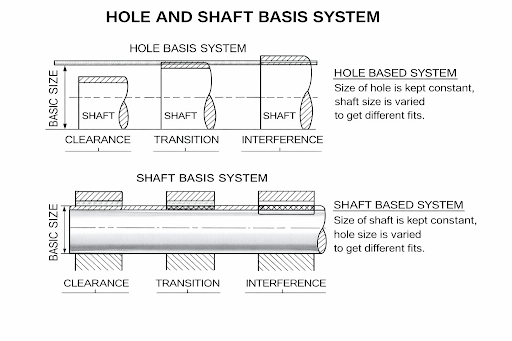
The Basics: Holes, Shafts, and Tolerances
Most fit discussions use a simple pair: a hole and a shaft. The hole might be in a housing or plate, and the shaft might be a pin, axle, or bearing seat. Each has a nominal size (the target), like 20.00 mm, and then a tolerance (the allowed variation).
Example idea:
- A hole might be allowed to be 20.00 to 20.03 mm.
- A shaft might be allowed to be 19.97 to 20.00 mm.
Because of tolerances, sometimes you get a gap, and sometimes you get a squeeze. The “worst case” sizes are what define the fit category:
- Biggest shaft with smallest hole (tightest case)
- Smallest shaft with biggest hole (loosest case)
Designers often use a shaft and hole tolerance chart to pick standard size bands that are easy to inspect and repeat. Standard systems (like ISO/ANSI fits) help different suppliers make parts that still assemble the same way.
A Quick Number Example You Can Picture
Let’s say the design calls for a 20 mm shaft in a 20 mm hole.
Case A: the hole is 20.02–20.05 mm and the shaft is 19.96–19.99 mm. Even if you get the smallest hole and the biggest shaft, you still have at least 0.03 mm of space, so it will assemble easily and can move.
Case B: the hole is 20.00–20.02 mm and the shaft is 19.99–20.01 mm. Now some pairs will have a tiny gap and some will have a tiny squeeze. That means the assembler might sometimes push it in by hand and sometimes need a light press.
Case C: the hole is 19.98–20.00 mm and the shaft is 20.01–20.03 mm. In every pairing, there is overlap, so you must use controlled force or temperature methods, and you should check stresses so you don’t split the outer part.
What are Clearance fits?
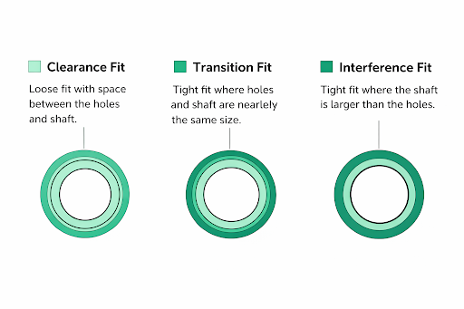
A clearance fit is when the hole is always larger than the shaft, even in the tightest case. This guarantees there is always a small gap between the two parts.
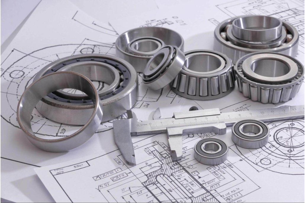
Clearance fits are used when you want easy assembly and free movement between parts. Common examples include a bolt passing through a hole, a shaft rotating inside a bearing, or a rod sliding in a guide.
Where Clearance Fits Are Used
- Rotating shafts and bushings
- Bearings that require lubrication
- Pistons inside cylinders
- Sliding machine components
- Bolted joints and removable parts
These fits are widely used in automotive components, pumps, gearboxes, and general machinery assemblies.
Manufacturing and Assembly Processes
- Bearings: Allow shafts to rotate smoothly without binding or excessive friction.
- Linkages and sliding parts: Enable easy movement and simple assembly with minimal force.
- Gears: Provide enough space for smooth rotation while avoiding tight metal-to-metal contact.
- Plumbing and pipe fittings: Allow pipes to slide into connectors for straightforward assembly and disassembly.
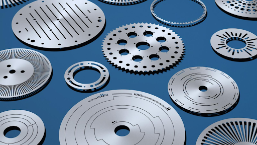
- Fabricated parts: holes created by laser cutting are often finish-machined to achieve the correct clearance
What Clearance Fits Are Good For
- Sliding and rotating parts that must move during use
- Assemblies that must go together quickly
- Designs that need space for lubrication, dirt, or thermal expansion
Clearance fits can be loose or tight. Loose running fits allow more movement, while close sliding fits provide better guidance and alignment.
What Are Transition Fits?
A transition fit is when the tolerance ranges of the hole and shaft overlap, so the assembly may result in either a small clearance or a small interference, depending on the actual part sizes.
Transition fits are chosen when accurate positioning is needed without fully locking the parts together.
Where Transition Fits Are Used
- Tooling fixtures: Ensure precise alignment while allowing controlled assembly and removal.
- Precision assemblies: Used in engines and machinery where tight control and accurate fit are critical.
- Bearings: Help limit movement between inner and outer races without creating excessive friction.
These fits are commonly used in precision machinery and CNC-machined assemblies where alignment matters.
Manufacturing and Assembly Processes
- Holes: precision boring, reaming, honing
- Shafts: precision turning and cylindrical grinding
- Assembly: hand push or light press
What Are Interference Fits?
An interference fit is when the shaft is always larger than the hole, creating intentional overlap. The parts must be forced together or assembled using heat or cooling.
Interference fits are used when parts must stay fixed and transmit high loads or torque.
Where Interference Fits Are Used
- Press-fit assemblies: Create strong, immobile joints without the need for fasteners.
- Gears and pulley systems: Lock components tightly onto shafts to prevent slipping during operation.
- Bearing assemblies: Secure inner or outer races to stop unwanted rotation or movement.
- Automotive wheel hubs: Maintain a firm and reliable connection between the wheel and axle.
Manufacturing and Assembly Processes
- Holes: precision boring and honing
- Shafts: grinding and heat treatment
- Fabricated housings produced through metal fabricationprocesses are often finish-machined before press-fitting
- Assembly: hydraulic press, mechanical press, or thermal fitting
Clearance Fit vs Interference Fit
Here’s the simplest comparison: clearance fits always have space, so parts can move, and assembly is easy. Interference fits always have overlap, so parts lock together, and assembly needs force or temperature control. Transition fits sit between them when you want a good location without a fully locked joint.
How These Fits Are Assembled in Real Life
In real manufacturing environments, different fit types require different assembly methods. Most workshops use a mix of the following approaches, depending on how tight the fit is.
- Hand assembly: Common for clearance fits and some transition fits where parts slide together easily without force.
- Light tapping: Used occasionally for transition fits when parts need gentle seating. Soft tools and proper support are important to avoid damage.
- Mechanical pressing: Arbor presses or hydraulic presses are used for controlled and repeatable assembly, especially for tighter transition fits and interference fits.
- Thermal assembly: The outer part is heated to expand the hole, or the inner part is cooled to shrink it. This method reduces assembly force and is often used for interference fits.
Fit Standards and Tolerances
In industry, fit types are controlled using internationally recognized standards so that parts manufactured by different companies, machines, or countries will still assemble correctly. These standards define how much a hole or shaft is allowed to vary in size and how those variations create clearance, transition, or interference fits.
The two main standards used worldwide are:
- ISO 286 – ISO system of limits and fits (used internationally)
- ANSI B4.1 – Preferred Limits and Fits (commonly used in the United States)
Both standards are based on the same principle: parts are made to a nominal size, and allowable size variation is controlled using tolerance bands.
A tolerance band is the acceptable range of size variation around the nominal dimension.
For example:
- A hole defined as 20.00 mm +0.02 / 0.00 means the hole size can range from 20.00 mm to 20.02 mm.
- A shaft defined as 20.00 mm 0.00 / −0.01 means the shaft size can range from 19.99 mm to 20.00 mm.
When these tolerance bands are combined, they determine whether the final assembly will result in a clearance, transition, or interference fit.
ISO Fit Designation System (ISO 286)
The ISO system uses a letter and number combination to describe tolerances:
- Capital letters (H, G, F, etc.) are used for holes
- Lowercase letters (h, g, f, etc.) are used for shafts
- The number (such as 6, 7, or 8) represents the International Tolerance grade (IT grade)
Lower IT numbers indicate tighter tolerances and higher precision, while higher numbers allow looser tolerances and easier manufacturing.
ANSI Fit Designation System (ANSI B4.1)
The ANSI system classifies fits into functional categories rather than letter-number pairs. Each class represents a typical application and tolerance range, making it easier to select fits based on use rather than calculation.
ANSI fits are grouped into:
- Running and Sliding Fits
- Locational Fits
- Force and Shrink Fits
Common Fit Standards and Classifications (Table)
| Standard | Fit Class / Code | Fit Type | Typical Application |
| ISO 286 | H8 / f7 | Clearance Fit | Sliding shafts, removable bushings |
| ISO 286 | H7 / g6 | Close Clearance Fit | Precision bearings, rotating shafts |
| ISO 286 | H7 / h6 | Locational Clearance Fit | Accurate positioning with free assembly |
| ISO 286 | H7 / k6 | Transition Fit | Couplings, locating pins |
| ISO 286 | H7 / m6 | Light Interference Fit | Gears, hubs requiring accurate alignment |
| ISO 286 | H7 / p6 | Interference Fit | Permanent gear and hub assemblies |
| ISO 286 | H7 / s6 | Heavy Interference Fit | High-torque press-fit joints |
| ANSI B4.1 | RC1–RC9 | Clearance (Running) Fits | Bearings, sliding components |
| ANSI B4.1 | LC1–LC5 | Locational Fits | Accurate positioning assemblies |
| ANSI B4.1 | LT1–LT5 | Transition Fits | Moderate press or snug fits |
| ANSI B4.1 | FN1–FN5 | Interference (Force) Fits | Press fits, shrink fits, hubs |
Fit Selection Factors
Choosing a fit is not just about picking one type or another; it requires consideration of several real-world factors:
- Function of the assembly: If parts must rotate or slide, a clearance fit is often best. If parts must not move relative to each other, an interference fit is ideal. Transition fits are suitable when precise alignment is necessary but full locking is not.
- Load and operating conditions: Heavy loads, shock forces, or torque require stronger connections, often requiring interference fits to prevent movement.
- Assembly and disassembly needs: If regular maintenance or part replacement is expected, designers prefer fits that assemble and disassemble with minimal damage. Clearance and many transition fits satisfy this requirement.
- Manufacturing capability: The process used to make the parts must be able to reliably produce the tolerances needed. Very tight fits require precision grinding and thorough inspection, which increases cost.
- Cost constraints: Tighter tolerances increase manufacturing cost due to slower machining, more advanced tools, and more inspection. A good fit balances function with cost efficiency.
Material and Temperature Effects on Fits
Materials behave differently under stress and temperature changes. Metals expand when heated and contract when cooled. A fit that is perfect at room temperature might become too tight at operating temperature or become loose in cold conditions.
For example, steel has a known expansion rate with temperature, and aluminum expands faster than steel. If a steel shaft is fitted into an aluminum housing, designers must account for differences in thermal expansion to prevent the assembly from binding or loosening during operation.
Material hardness also affects fit behavior. Softer materials can deform more easily, which might be desirable in some interference fits where materials must compress slightly. Surface finish also matters: smoother surfaces require less force to assemble and reduce wear over time.
Considering temperature and material effects during design ensures that fits remain reliable under actual operating conditions.
Fit Types For Bearings
Bearings are a special case because they dislike both looseness and distortion. If a bearing ring can “walk” on its seat, it can wear the shaft or housing. But if you squeeze the bearing too much, you can reduce its internal clearance and create heat and early failure. A practical approach is to make the ring that sees a rotating load tighter, and keep the other ring easier to assemble, while following the bearing manufacturer’s guidance for your speed, load, and temperature.
Comparison Table of the Three Fit Types
| Feature | Clearance Fit | Transition Fit | Interference Fit |
| Size relationship | Hole always larger than shaft | Hole and shaft ranges overlap | Shaft always larger than hole |
| Assembly method | Easy, hand assembly | Manual or light press | Pressing or thermal methods |
| Movement after assembly | Free movement | Limited or no movement | No movement allowed |
| Accuracy | Lower | Medium | High |
| Load capacity | Low to medium | Medium | High |
| Disassembly | Easy | Moderate | Difficult |
| Typical uses | Bearings, sliding shafts | Locating pins, precision alignment | Gears, hubs, powerful torque joints |
How to Call Out Fits on Drawings
You can communicate fits by giving hole and shaft limits, using a standard fit code, and adding a short functional note like “must slide freely” or “must not slip under torque.” That small note helps everyone understand the intent.
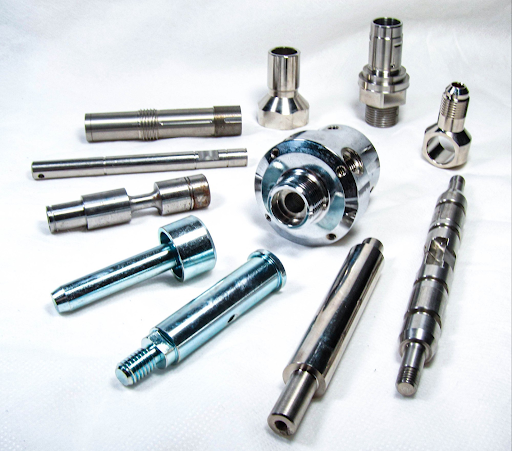
Kirmell’s Manufacturing Services and Fit-Critical Components
At Kirmell, we manufacture precision metal components where correct fits, tolerances, and assembly performance matter. Our services include metal pressing, welding, and CNC machining, allowing us to produce parts with controlled hole and shaft dimensions suitable for clearance, transition, and interference fits. These capabilities ensure components assemble correctly, perform reliably, and meet demanding industrial requirements.
We also support complete metal fabrication processes, including laser cutting for accurate profiles and welded assemblies that are finish-machined where tight fits are required. By combining fabrication, machining, and inspection under one roof, Kirmell helps customers achieve consistent fit quality across prototypes, batch production, and long-term manufacturing programs.
Need components with accurate fits and reliable performance?
Contact Kirmell to discuss your project and find out how our precision manufacturing and metal fabrication services can support your requirements from design through to production.
Conclusion
Clearance, transition, and interference fits define how parts assemble and perform in real manufacturing. Selecting the correct fit ensures components move freely when required, align accurately, or remain securely fixed under load. The right choice helps prevent wear, vibration, and assembly issues while improving reliability.
Good fit design is about matching function, tolerance, and manufacturing capability—not making parts unnecessarily tight. When fits are selected correctly and produced with controlled processes, they lead to consistent quality, efficient assembly, and long-lasting mechanical components.
FAQs
What is the main difference between clearance, transition, and interference fits?
How do I know which fit type to choose for my part?
Are tighter fits always better?
Why are tolerances important when designing fits?
How does temperature affect fits?